About New Japan Radio
- Location:Japan
- To aid in the healthy development of society by accomplishing our focal role in matching the expectations of society with those of our customers
- To realize our corporate mission by providing the best products possible based on our unique "microelectronics and microwave" technologies

- Fusing these two "?" technologies and achieving even more significant progress are the major missions of New Japan Radio (New JRC), which focuses on the multimedia age
- In the 21st century when the world of multimedia is vast, we have set our sights on further development of information technology and audiovisuals.
- "?&?" limitlessly brings closer two types of "?", semiconductor technology and microwave technology which have been developing separately
- The fusion of these two technologies allows a dramatic expansion of multimedia possibilities.
- New Japan Radio will continue to contribute to both industry and society with a corporate strategy that envisions the future and foresees the
pioneering high-level technologies in this rapidly evolving field.
- With "?&?" as our slogan, New JRC ventures into the development of microelectronics technology as well as microwave technology.
Product Highlights
| Picture |
Description |
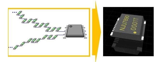
Integration of resistor Network |
Datasheet |
NJU7890 |
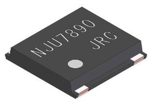 |
Voltage Measurement up to 1000 V
- Operation Voltage Range 2.2V to 5.5V
- Common Mode Input Voltage Range +1000 V (continuous)
- Differential Input Voltage +1000 V (continuous)
- High Precision Attenuation Rate ±1% (Ta=-40 to +125ºC)
- High Input Resistance 30MΩ
- Enhanced RF noise immunity
- Package PMAP11
|
 |

Datasheet

NJU7890 News Release |
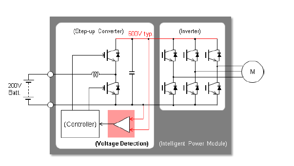
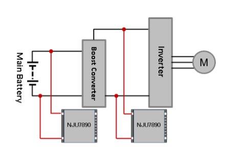
NJU7890 Application Example:
- Power Control Unit (PCU)
- Inverter Control
|
 |
 |
NJU9103
| Picture |
Features |
Description |
Datasheets |
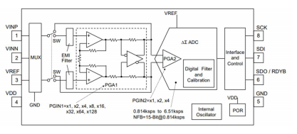 |
- Operating Voltage Range: 2.7 to 3.6V
- Ambient Operating Temp.: -40°C to +125°C
- ADC Resolution: 16bit no missing codes
- Data Rate: 0-814k to 6.51ksps
- Input Modes: Differential, Single-ended, Pseudo-differential
- PGA Gain: x1 to x512
- Conversion Mode: Single – or Continuous conversion
- Interface: SPI
- Package: DFN8 (ESON8-V1) / 2.3mm x 2.3mm, SSOP8 / 3.5mm x 6.4mm
|
Member of New Japan Radio’s Analog Front End Lineup and incorporates a wealth of integrated features optimized to build all kind of fast, precise, and compact sensors |
|
Products
Radar Sensors
| Picture |
Description |
Links |
K-Band Distance Measurement Sensor Module NJR4234BW |
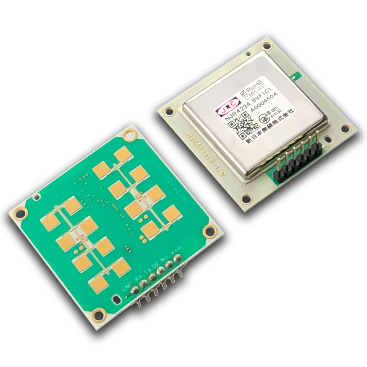 |
- 24 GHz FMCW radar sensor
- 2m to 30m detection range
- Detection of up to 3 moving objects
- Integrated antenna, microwave RF circuit, base-band IF circuit and MCU for signal processing
- UART interface for simple configuration
|
|
K-band Intelligent Doppler Module NJR4266
Series |
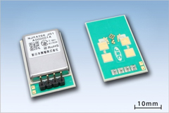 |
- Motion sensor using the 24GHz Microwave Doppler
- Antenna, Microwave RF circuit, IF amp, MCU and voltage regulator are integrated in a low- profile package (17.2 x 27.3 x 5.1 mm)
- Low-power-consumption, minimum 1.9 mA @ 3.3 V power supply
- Sleep mode for reducing power when unnecessary
- Signal processing software for the steady sensing
- Enhancing the signal from movement object and decreasing random noises
- Decreasing the mutual interference between sensors
- Identification of direction for movement object (approaching and leaving)
- Interface selectable from UART and digital output / analog
- sensitivity setting
- Detection range up to 14m
|

|
| |
- New version NJR4266A3 Series
- For short detection range up to 80cm
|
|
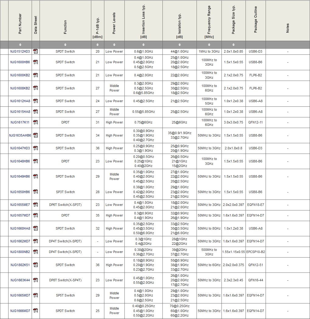
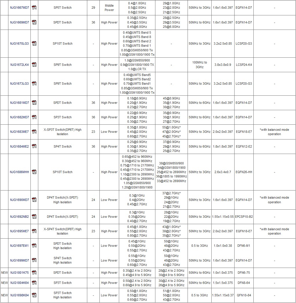
RF Switches
Low Noise Amplifier
Low Noise Amplifiers | Front-End Modules
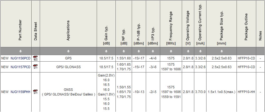
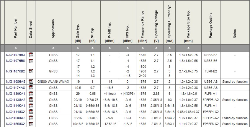
Low Noise Amplifiers | GNSS
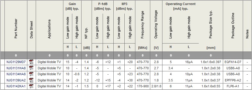
Low Noise Amplifiers | Digital Mobile TV
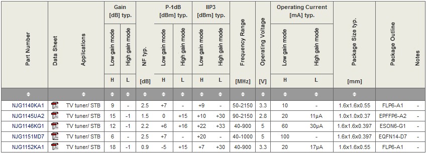
Low Noise Amplifiers | TV tuner/STB
Low Noise Amplifiers | 3G/LTE

Content
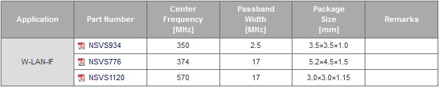
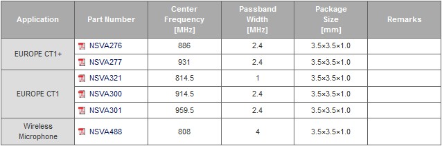
SAW Filter
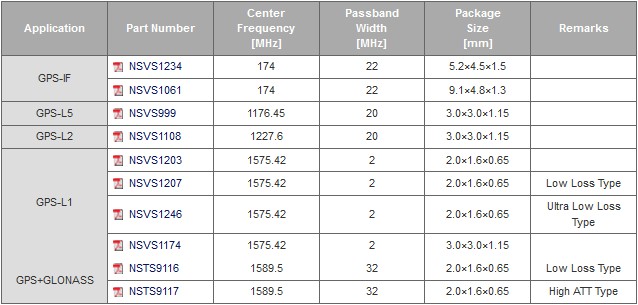
GPS
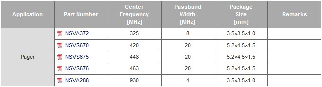
Pager
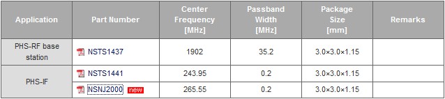
PHS/Mobile Phone
Automotive
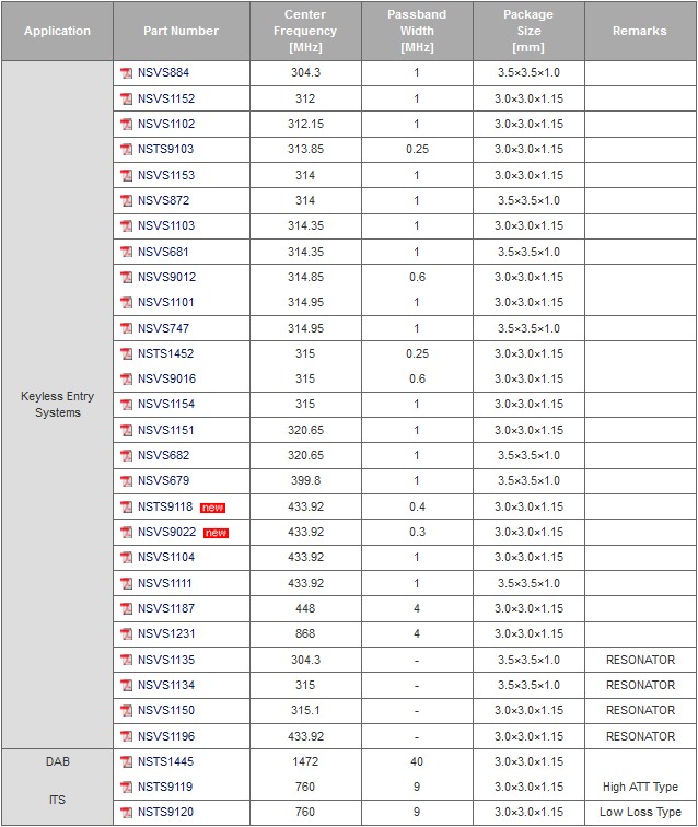
Wireless LAN
Cordless Phone
Low Power Transceiver

Content
DC Brush Motor / Actuator Drivers

Content
Stepper Motor Driver
Bipolar Stepper Motor Drivers
| P/N |
Current
(peak)
(rms) |
Motor
Voltage |
Logic
Voltage |
No of
Motors |
Input |
Mode |
Vref
In |
Current
scaling |
Package |
| NJM13775 |
0,5A
0,35A |
10..40V |
5V |
1 |
Phase+EN |
2/1-2 |
X |
- |
LQFP48 |
| NJM2670 |
1,5A
1,3A |
4..55V |
5V |
1 |
2IN+EN |
2/1-2 |
- |
- |
DIP22, SOP24 |
| NJM2673 |
1,0A |
4..40V |
5V |
0,5 |
Phase+Ix |
2/1-2/W1-2 |
X |
2bit |
SOP24 |
| NJM2675 |
1,5A |
4..55V |
5V |
0,5 |
2IN+EN |
2/1-2 |
- |
- |
SOP16 |
| NJM3717 |
1,2A |
10..45V |
5V |
0,5 |
Phase+Ix |
|
X |
2bit |
DIP16, SOP20, PLCC28 |
| NJM3770A |
1,8A |
10..40V |
5V |
1 |
Phase+Ix |
|
X |
2bit |
DIP16, SOP20, PLCC28 |
| NJM3771 |
0,7A |
10..40V |
5V |
1 |
Phase |
2 |
X |
- |
DIP22, SOP24, PLCC28 |
| NJM3772 |
1,2A |
10..40V |
5V |
1 |
Phase |
2 |
X |
- |
DIP22, PLCC28 |
| NJM3773 |
0,85A |
10..40V |
5V |
1 |
Phase+EN |
2/1-2 |
X |
- |
DIP22, SOP24 |
| NJM3774 |
1,2A |
10..40V |
5V |
1 |
Phase+EN |
2/1-2 |
X |
- |
DIP22, SOP24, PLCC28 |
| NJM3775 |
0,85A |
10..40V |
5V |
1 |
Phase+EN |
2/1-2 |
X |
- |
SOP24 |
| NJM3777 |
0,9A |
10..40V |
5V |
1 |
Phase+EN |
2/1-2 |
X |
- |
SOP24 |
| NJM6219 |
1,0A |
4..40V |
5V |
1 |
Phase+Ix |
2/1-2/W1-2 |
X |
2bit |
SSOP32 |
| NJU7384 |
0,7A |
4..8V |
3,3/5V |
1 |
Step/Dir |
2/1-2 |
- |
- |
SSOP20 |
| NJU7385 |
0,7A |
3..8V |
3..5V |
1 |
Phase+EN
2IN |
2/1-2 |
- |
- |
ESSOP16, QFN16-JE |
| NJU7381A |
0,4A |
1,8..5,5V |
|
1 |
2IN |
2/1-2 |
- |
- |
EQFN16-JE |
| NJU7382A |
0,4A |
1,8..5,5V |
|
1 |
Phase+EN |
2/1-2 |
- |
- |
SDIP22, SSOP32 |
| NJW4375 |
0,8A (B)
1,5A U) |
9..36V |
3,3/5V |
1 |
SPI |
2/1-2 |
X |
data |
SDIP22, SSOP32 |
Content
Datasheets
Unipolar Stepper Motor Drivers

Stepper Motor Controllers

BLDC Motor ICs

BLDC Overview |
Three-Phase BLDC Motor Pre-Drivers

| Pictures |
Features / Description |
Links |
Highlight: NJW4315 BLDC-Predriver |


|
- Low Quiescent Current (IDD=3.2mA typ. @ VCC=24V)
- HALL-Sensor Inputs
- Rotor Position Decoder
- Control Types: DC-Input, PWM-Input
- Lock Protection: Auto Recovery, Latching
- Forward / Reverse Function
- Current Limit
- Thermal Shutdown
- Under Voltage Lockout
The NJW4315 is a 3-Phase Brushless DC Motor pre-driver IC with 120 turn-on. The NJW4315 generates 3 phase sequence based on external hall
signal input and drives power MOSFETS. It features wide operating voltage range from 6.3V to 36V, small package and wide temperature range.
|
|
Three-Phase BLDC Motor Controllers

Single-Phase BLDC Motor Drivers

Two-Phase Unipolar BLDC Motor Pre-Drivers

FET Gate Driver for General Motor Application

Power Management
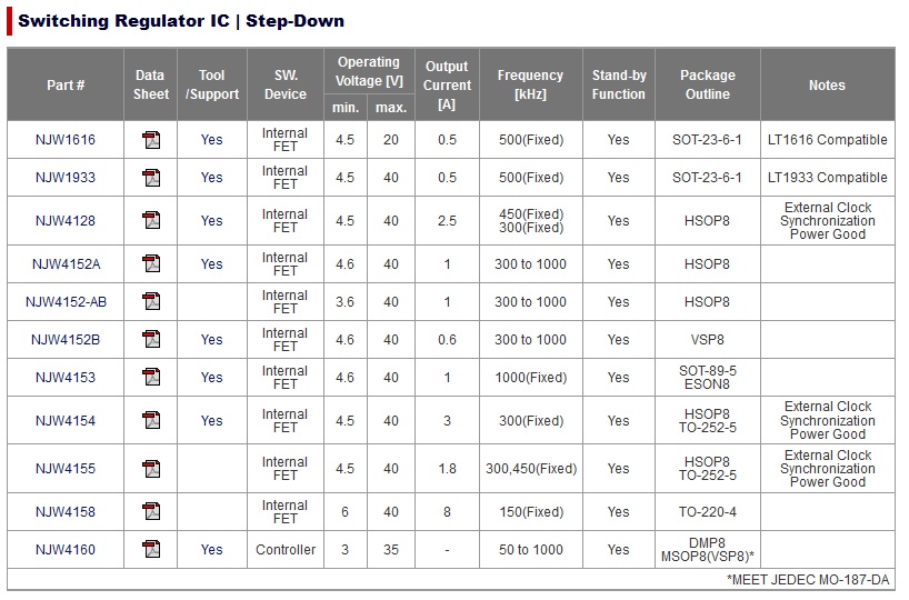
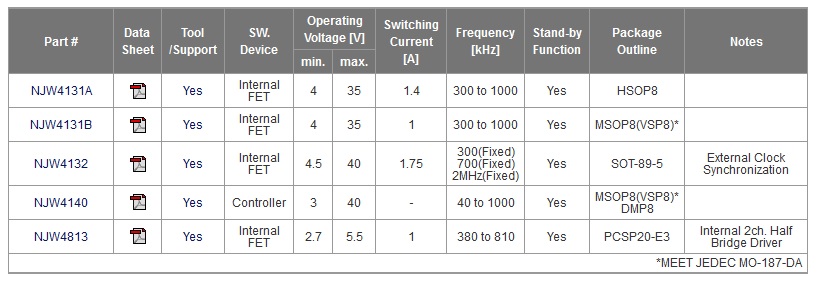
Switching Regulators Step-down
Switching Regulators Step-Up
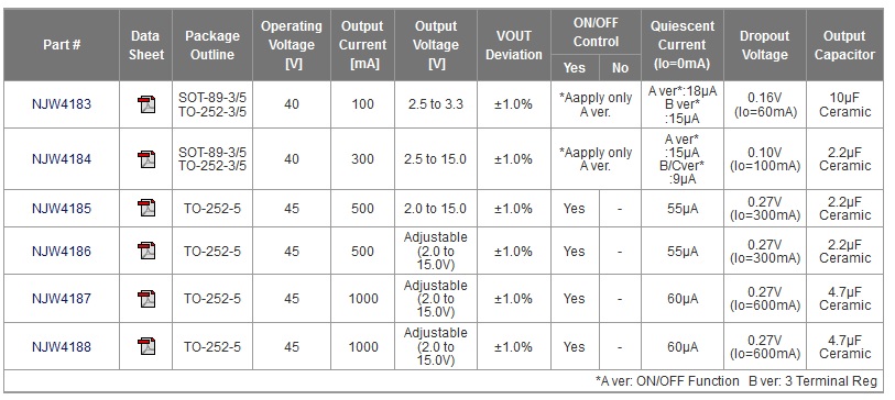
Low dropout Regulator Series
LED Driver for Backlight

Interfaces
SPI - Serial Peripheral Interface
The Serial Peripheral
Interface or SPI
bus is a synchronous serial data link, a de facto standard, named by Motorola, that operates in full duplex mode. It is used for short
distance, single master communication, for example in embedded systems, sensors, and SD cards.
Devices communicate in master/slave mode where the master device initiates the data frame. Multiple slave devices are allowed with individual slave
select lines. Sometimes SPI is called a four-wire serial bus, contrasting with three-, two-, and one-wire
serial buses. SPI is often referred to as SSI (Synchronous Serial Interface).
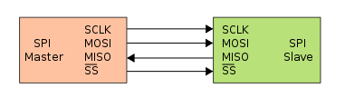
The SPI bus specifies four logic
signals:
SCLK : Serial Clock (output from master).
MOSI : Master Output, Slave Input (output from master).
MISO : Master Input, Slave Output (output from slave).
SS : Slave Select (active low, output from master).
Source: www.wikipedia.org
Step/Direction
Step/Direction, Step/Dir, Pulse/Direction, Clock/Direction or CLK.
The Direction signal set the direction of rotation and each pulse on the Step
signal causes the controller to move the motor one step in that direction.
The controller translates these signals into different patterns of current flow in the coils, which result in the moment of the motor.

The pulse frequency of the Step signal defines the motor speed. Depending on the setting of the Stepper Motor Driver the Step signal is taken as
fullstep, halfstep or microstep signal.
Phase+EN
2IN+EN
2 Inputs + Enable
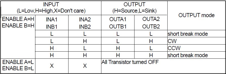
CW = Counter Wise
CCW = Counter Clock Wise
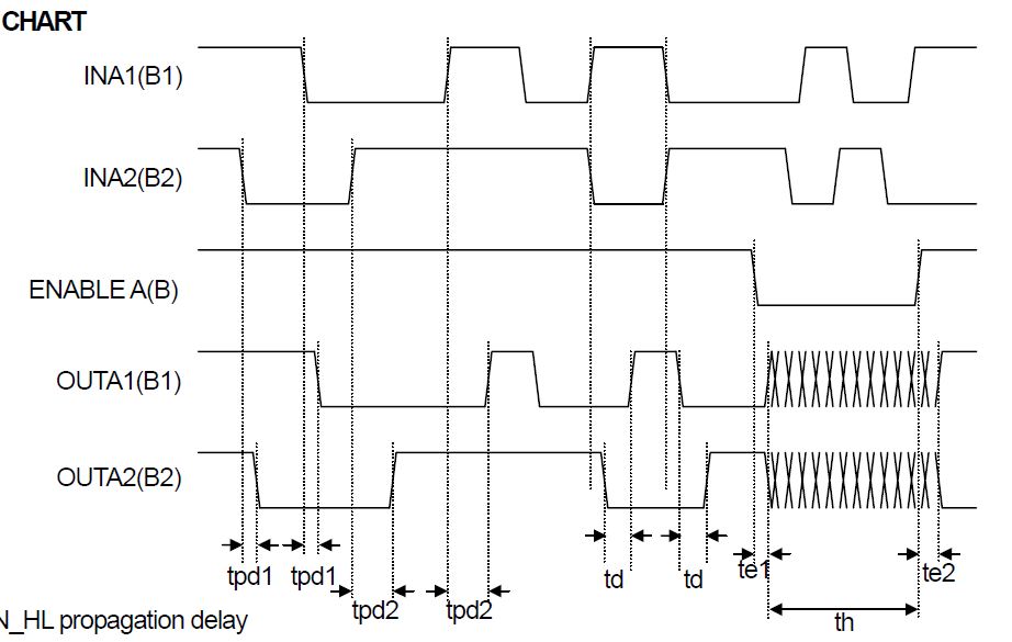
Phase+Ix
Phase input
The phase input determines the direction of the current in the motor winding. High input forces the current from terminal
MA to MB and low input from terminal MB to MA. A Schmitt trigger provides noise immunity and a delay circuit eliminates
the risk of cross conduction in the output stage during a phase shift.
Half- and full-step operation is possible.
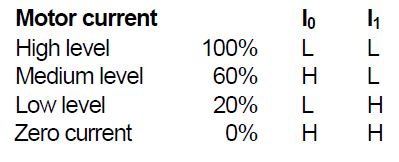
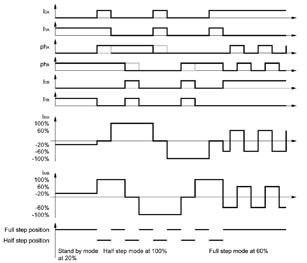
Current level selection.
The status of I0 and I1 inputs determines the current level in the motor winding. Three fixed current levels can be
selected according to the table below.
Phase
2IN
2 Input Control Mode
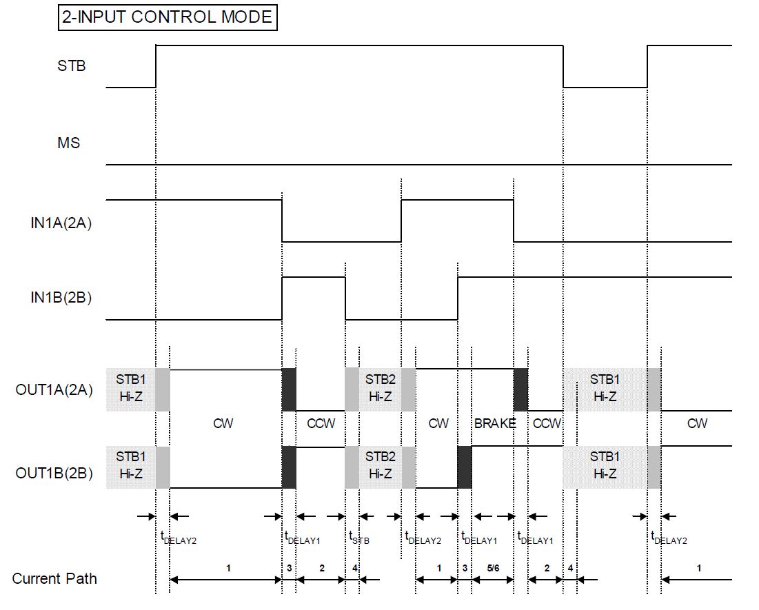
Phase+Direction
For every motor phase thre are two inputs: an analog value for the current (Phase A+B) and the direction of the current of the phase (SignA+B).
Using the analog/parallel interface it is necessary to generate an analog value for the motor current.
IIC or I²C
I²C (Inter-Integrated Circuit), pronounced I-squared-C, is a multi-master, multi-slave, single-ended, serial
computer bus invented by Philips Semiconductor, known today as NXP Semiconductors, used for attaching low-speed peripherals to computer
motherboards and embedded systems. Alternatively I²C is spelled I2C (pronounced I-two-C) or IIC (pronounced I-I-C).
Since October 10, 2006, no licensing fees are required to implement the I²C protocol. However, fees are still required to obtain I²C
slave addresses allocated by NXP.
Some companies are using also the term TWI (Two-Wire-Interface).
I²C uses only two bidirectional open-drain lines, Serial Data Line (SDA) and Serial Clock Line (SCL), pulled up with resistors.
Typical voltages used are +5 V or +3.3 V although systems with other voltages are permitted.